
CFM Calculator: Calculate Ventilation and Duct Airflow
Pick your method first, then apply the matching formula. For ventilation sizing, use the ACH method: CFM = (L × W × H × ACH) / 60. For HVAC equipment sizing, use the sensible-heat formula: CFM = Q / (1.08 × ΔT). For duct checks, use the continuity equation: CFM = Area (ft²) × Velocity (FPM). ASHRAE 62.1 governs commercial outdoor-air requirements; ASHRAE 62.2 covers residential. For quick results, online CFM calculators from OmniCalculator, Workiz, and IndustrialFansDirect handle all three methods with unit conversions built in.
- ACH method: Best for ventilation screening, early-stage estimates, and residential spaces.
- Sensible-heat method: Required for sizing supply airflow to meet a calculated thermal load.
- Duct-velocity method: Used to verify or design duct cross-sections against a target flow rate.
Key figure: ASHRAE 62.1 and 62.2 are the authoritative North American standards defining minimum outdoor-air and indoor air quality requirements for both commercial and residential construction.
Key Takeaways
Accurate CFM calculation requires choosing the right method first, applying ASHRAE guidance for North American projects, correcting for altitude above 2,000 ft, and verifying delivered airflow with TAB after installation.
| Point | Details |
|---|---|
| Pick the method first | ACH for ventilation screening, sensible-heat for equipment sizing, duct-velocity for duct design. |
| Apply ASHRAE standards | Use ASHRAE 62.1 for commercial and 62.2 for residential; supply the larger of load-based or outdoor-air CFM. |
| Correct for altitude | Above 2,000 ft, use CFM = Q_s / (14.4 × ρ_alt × ΔT) — the standard 1.08 constant underestimates required airflow. |
| Expect delivery losses | Plan for 15–30% lower delivered CFM than rated; flex duct typically loses about 15% vs rigid. |
| Verify with TAB | Measure actual CFM at diffusers after installation and reconcile against design targets and ASHRAE minimums. |
Table of Contents
- What are the three CFM formulas you need?
- How do you calculate CFM using room dimensions?
- How do you calculate CFM from a BTU/hr sensible load?
- How do you find CFM from duct size and velocity?
- What ACH values and ASHRAE guidance apply in North America?
- How do you convert CFM to L/s and m³/h?
- Worked examples: apply the formulas to real scenarios
- What real-world factors reduce delivered CFM?
- How do you use an online CFM calculator?
- The part most CFM guides get wrong
- How Highlevelcrm-rconstructionsolutions helps contractors manage HVAC scope
- Sources
What are the three CFM formulas you need?
Every airflow calculation in HVAC and ventilation work traces back to one of three formulas. Here they are as a one-page reference.
ACH / room-volume formula
CFM = (L × W × H × ACH) / 60
- Compute room volume: V (ft³) = Length × Width × Height
- Multiply by the target air changes per hour (ACH)
- Divide by 60 to convert from ft³/hr to ft³/min
The ACH method is the standard starting point for ventilation sizing and early-stage estimates.
Sensible-heat (load-based) formula
CFM = Q_s / (1.08 × ΔT)
The constant 1.08 comes from 60 × 0.075 (air density, lb/ft³) × 0.24 (specific heat, BTU/lb·°F) at standard sea-level conditions. Q_s is the sensible heat load in BTU/hr; ΔT is the supply-to-room temperature difference in °F.
Duct-velocity formula
CFM = Area (ft²) × Velocity (FPM)
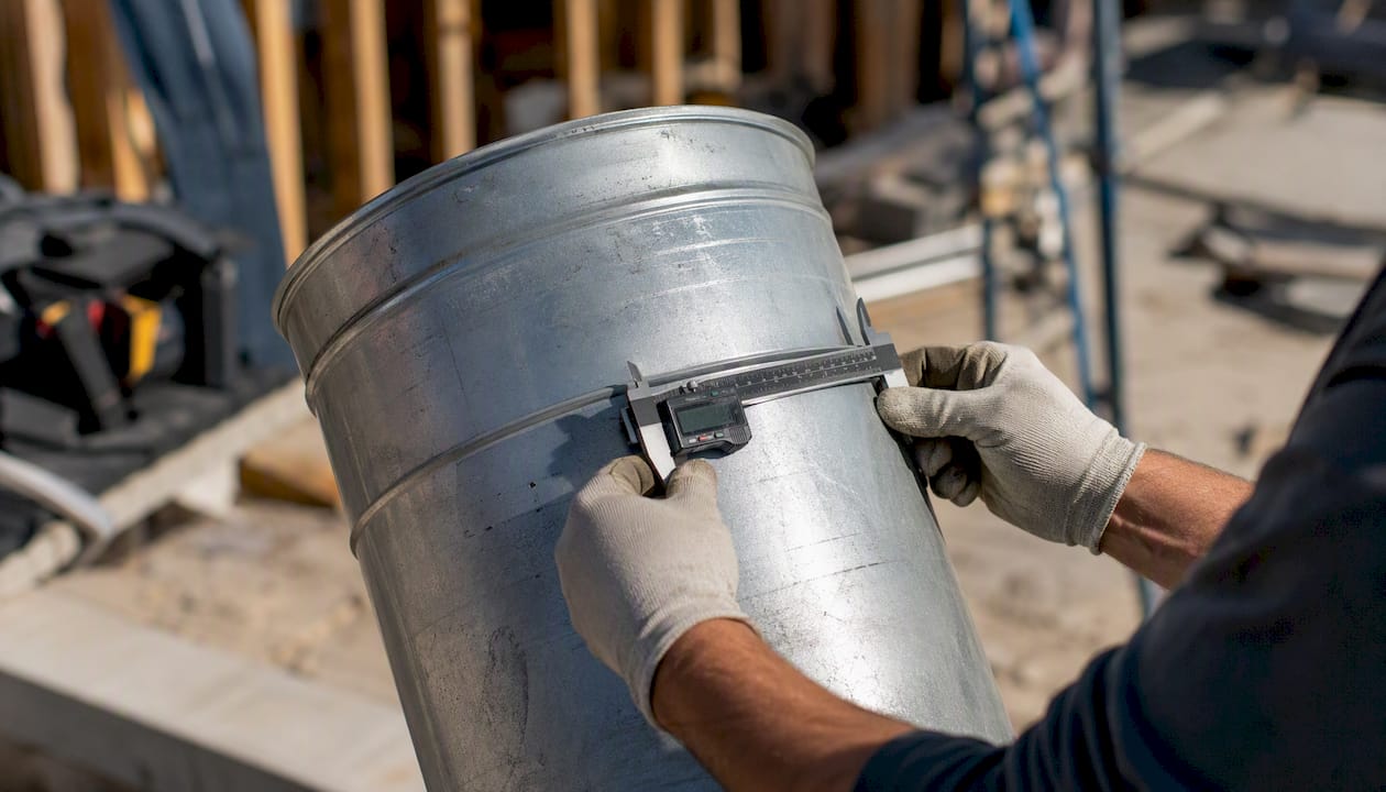
- Round duct: A = π × (D/2)², where D is diameter in feet
- Rectangular duct: A = Width (ft) × Height (ft)
Conversion hints:
Rule of thumb: residential and light-commercial systems typically require around 400 CFM per ton of cooling capacity as a common design target.
How do you calculate CFM using room dimensions?
The ACH method is the fastest way to get a ventilation number from a tape measure and a code table.
- Measure the room. Record length, width, and ceiling height in feet.
- Calculate volume. Multiply L × W × H to get cubic feet.
- Choose an ACH value. Use the table in the ASHRAE guidance section below, or your local code. A standard bedroom uses 4–6 ACH; a bathroom uses 8 ACH or more.
- Apply the formula. CFM = (Volume × ACH) / 60.
- Check against code. For commercial projects, confirm the result against ASHRAE 62.1 outdoor-air requirements — ACH alone does not satisfy the Ventilation Rate Procedure.
Worked example — 12 × 12 × 8 bedroom at 4 ACH:
- Volume = 12 × 12 × 8 = 1,152 ft³
- CFM = (1,152 × 4) / 60 = 4,608 / 60 = 76.8 CFM
Round to 77 CFM for equipment selection. That number is a screening result. For commercial compliance, the ASHRAE 62.1 Ventilation Rate Procedure uses occupant density and floor area together, not ACH alone.
Pro Tip: ACH is a useful screening tool, but treat it as a floor, not a ceiling. If your load-based calculation or ASHRAE outdoor-air requirement produces a higher number, use that higher number.
How do you calculate CFM from a BTU/hr sensible load?
When you have a calculated heat load, the sensible-heat formula gives you the supply airflow needed to handle it.
CFM = Q_s / (1.08 × ΔT)
- Q_s: Zone sensible load in BTU/hr (from Manual J or your load calculation)
- ΔT: Difference between supply air temperature and room setpoint (°F)
- 1.08: The standard constant at sea level (60 × 0.075 × 0.24)
Altitude correction matters. Above roughly 2,000 ft, air density drops and the 1.08 constant underestimates required airflow. Use the density-adjusted form:
CFM = Q_s / (14.4 × ρ_alt × ΔT)
where ρ_alt is the actual air density at your site elevation in lb/ft³.
Worked example — sea level vs. Denver (5,280 ft):
- Zone load: 24,000 BTU/hr; ΔT: 20°F
- Sea level: CFM = 24,000 / (1.08 × 20) = 24,000 / 21.6 = 1,111 CFM
- Denver (ρ_alt ≈ 0.062 lb/ft³): CFM = 24,000 / (14.4 × 0.062 × 20) = 24,000 / 17.86 = 1,343 CFM
That 232 CFM difference is not trivial when you are selecting a fan or sizing a duct. Always compare your load-based CFM to ASHRAE 62.1 outdoor-air requirements and supply the larger of the two. If the outdoor-air requirement exceeds your thermal supply, you may need a dedicated outdoor-air system (DOAS).
How do you find CFM from duct size and velocity?
The continuity equation connects duct geometry to airflow. If you know two of the three variables (CFM, area, velocity), you can solve for the third.
CFM = Area (ft²) × Velocity (FPM)
- Round duct (12-in diameter at 800 FPM): A = π × (0.5)² = 0.785 ft²; CFM = 0.785 × 800 = 628 CFM
- Rectangular duct (12 in × 8 in at 700 FPM): A = 1.0 × 0.667 = 0.667 ft²; CFM = 0.667 × 700 = 467 CFM
Residential supply ducts typically target 600–900 FPM; commercial main trunks often run 1,000–1,500 FPM. Staying within these ranges keeps noise and static pressure manageable.
Common duct sizes at typical velocities:
To invert the formula and find required duct diameter for a target CFM, rearrange: D = 2 × √(CFM / (π × Velocity)).
What ACH values and ASHRAE guidance apply in North America?
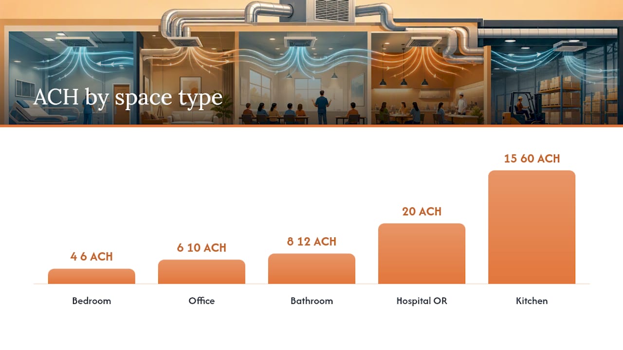
ACH benchmarks vary widely by space type. The table below gives typical ranges used in North American practice.
| Space Type | Typical ACH Range | Notes |
|---|---|---|
| Bedroom | 4–6 | Residential baseline |
| Bathroom | 8–12 | Exhaust fan sizing |
| Kitchen | 15–60 | Range hood dominates |
| Office | 6–10 | ASHRAE 62.1 governs OA |
| Classroom | 4–12 | Occupancy-driven |
| Hospital OR | 20 | Infection control |
ASHRAE 62.1 (commercial) uses the Ventilation Rate Procedure, not ACH. The formula is:
V_oa = R_p × P_z + R_a × A_z
- R_p = outdoor air per person (CFM/person); R_a = outdoor air per unit area (CFM/ft²)
- Office example: R_p = 5 CFM/person, R_a = 0.06 CFM/ft²
A 1,000 ft² office with 10 occupants would require: V_oa = (5 × 10) + (0.06 × 1,000) = 50 + 60 = 110 CFM of outdoor air minimum.
ASHRAE 62.2 (residential) applies to dwelling units and calculates whole-building mechanical ventilation differently, based on floor area and number of bedrooms rather than occupant density.
ASHRAE 62.1 and 62.2 are the authoritative North American standards for minimum outdoor-air and indoor air quality compliance. Always verify local Authority Having Jurisdiction (AHJ) requirements — some jurisdictions adopt earlier editions or add amendments. Treat ASHRAE as the floor, not the ceiling, for any code-driven project.
How do you convert CFM to L/s and m³/h?
The two conversion constants you need for every project that mixes metric and imperial units:
- 1 CFM = 0.471947 L/s
- 1 CFM = 1.69901 m³/h (CMH)
Inverse factors: 1 L/s = 2.119 CFM; 1 m³/h = 0.589 CFM.
Quick conversion lookup:
The 400 CFM/ton rule of thumb holds for standard conditions. In humid climates, designers often drop to 350 CFM/ton to improve dehumidification; in dry climates, 450 CFM/ton is common to maximize sensible cooling. Round field results to the nearest 5 CFM — false precision beyond that does not reflect actual system variability.
Worked examples: apply the formulas to real scenarios
Example 1: ACH ventilation check (living room)
- Room: 20 ft × 15 ft × 9 ft ceiling; target ACH = 6
- Volume = 20 × 15 × 9 = 2,700 ft³
- CFM = (2,700 × 6) / 60 = 270 CFM
Example 2: Sensible-heat sizing with altitude correction
- Zone load: 36,000 BTU/hr; ΔT = 20°F; site elevation: 5,000 ft (ρ_alt ≈ 0.063 lb/ft³)
- Sea level: CFM = 36,000 / (1.08 × 20) = 1,667 CFM
- Altitude-corrected: CFM = 36,000 / (14.4 × 0.063 × 20) = 36,000 / 18.14 = 1,985 CFM
- Cross-check: if ASHRAE 62.1 outdoor-air for this zone is 2,—, supply 2,— or add a DOAS.
Example 3: Duct check and diameter sizing
- Known: 10-in round duct at 850 FPM
- A = π × (0.417)² = 0.545 ft²; CFM = 0.545 × 850 = 463 CFM
- Invert for a target of 600 CFM at 800 FPM: D = 2 × √(600 / (π × 800)) = 2 × √(0.239) = 2 × 0.489 = 11.8 in → specify 12-in duct
What real-world factors reduce delivered CFM?
Rated fan CFM and delivered CFM are rarely the same number. Real-world delivery losses of 15–30% are common once duct friction, fittings, filters, and coil resistance are accounted for.
- Static pressure: Every elbow, filter, and coil adds resistance. Check the fan curve at your expected system static pressure — not at free-air conditions.
- Duct leakage: Even well-sealed systems lose airflow at joints and seams. Plan for it in your duct sizing.
- Flex duct: Flex duct typically delivers about 15% less airflow than rigid duct of the same diameter, especially when installed with sags or tight bends. Size up or use rigid where performance is critical.
- Filter loading: A dirty filter can cut delivered CFM significantly. Design for a loaded filter condition, not a clean one.
- TAB (testing, adjusting, balancing): TAB is the field verification step that confirms actual delivered airflow at each diffuser. For commercial projects, TAB is often a code requirement and always a best practice.
Pro Tip: *When designing a system, size ducts for the rated CFM and then verify at commissioning with a flow hood at each diffuser.
Commissioning checklist:
- Measure actual CFM at each supply and return diffuser with a flow hood
- Confirm outdoor-air damper positions and minimum stop settings
- Reconcile load-based supply CFM against ASHRAE outdoor-air minimums
- Document TAB results for the project record
How do you use an online CFM calculator?
Online airflow calculators handle unit conversions, altitude corrections, and multi-method outputs in seconds. Here is how to work through one efficiently.
- Select your calculation method — ACH, sensible-heat, or duct-velocity. Most calculators let you toggle between them.
- Enter room dimensions — length, width, and height in feet (or meters if the tool supports metric input).
- Input ACH or BTU load — use your code table for ACH, or your Manual J output for BTU/hr.
- Set ΔT — for sensible-heat calculations, enter the design supply-to-room temperature difference.
- Enter duct geometry — diameter or width × height, plus target velocity, for duct-velocity calculations.
- Specify altitude — if your site is above 2,000 ft, enter elevation so the tool can apply a density correction.
- Read all outputs — a good calculator returns CFM, L/s, m³/h, CFM/ton, and density-corrected values together.
Tools to try:
- OmniCalculator — fast, browser-based, covers ACH and duct methods with metric/imperial toggle; good for quick estimates.
- Workiz — field-service focused; useful for HVAC techs who need to log results alongside job records.
- IndustrialFansDirect — exhaust fan selection tool that pairs CFM output with product recommendations for industrial and commercial spaces.
Automated calculators that include altitude correction and CFM/ton diagnostics reduce manual errors and help narrow equipment ranges before detailed Manual J/D work. Always cross-check calculator outputs against ASHRAE or your design calculations before using them for code submissions or equipment selection.
The part most CFM guides get wrong
Most online CFM guides stop at the formula. They give you CFM = (L × W × H × ACH) / 60, show a worked example, and call it done. That is useful as far as it goes, but it skips the part that actually determines whether your system performs.
The real issue is the gap between calculated CFM and delivered CFM. A formula gives you a target. Your duct system, your filter, your coil, and your fan curve determine whether you hit it.
The second thing guides understate is the altitude correction. The 1.08 constant is taught as a universal fact, but it only holds at sea level. A contractor in Denver or Salt Lake City who uses 1.08 without adjustment is undersizing supply airflow by a meaningful margin. The density-adjusted formula is not complicated — it just requires knowing your site elevation and looking up the corresponding air density.
My honest recommendation: use an online CFM calculator for speed, but treat its output as a starting point. Cross-check against ASHRAE 62.1 outdoor-air requirements, verify your fan curve at expected static pressure, and plan for TAB before you close the ceiling. The calculation is the easy part. Delivering the number in the field is where the work actually happens.
How Highlevelcrm-rconstructionsolutions helps contractors manage HVAC scope

Ventilation calculations are one piece of a larger project puzzle. Capturing CFM targets, TAB documentation, mechanical change orders, and subcontractor communications in separate spreadsheets creates gaps that cost time and money.
Highlevelcrm-rconstructionsolutions is built specifically for contractors who need those pieces connected. With automated lead tracking, custom reporting dashboards, and workflow tools designed around construction operations, it gives your team a single place to manage mechanical scope from estimate through closeout. Explore the industries we serve to see how construction-specific CRM fits your operation.
Sources
These tools and references cover the full range from quick field estimates to code-compliant design.
- CFM Airflow Calculator — Size Ventilation, Ductwork & HVAC Loads with Precision — Calcexp
- CFM Airflow Calculator — ASHRAE 62.1 | EngineersUniverse
- Free Airflow CFM Calculator: HVAC Air Volume & Fan Law Simulator | Simulations4All
- ANSI/ASHRAE Standard 62.1 and 62.2 — ASHRAE
Contractors who need to capture ventilation scope, TAB documentation, and mechanical change orders in a single workflow can explore how construction estimating workflows connect HVAC design inputs to bids and project records.